Sunday, June 10, 2012

Halfway there.

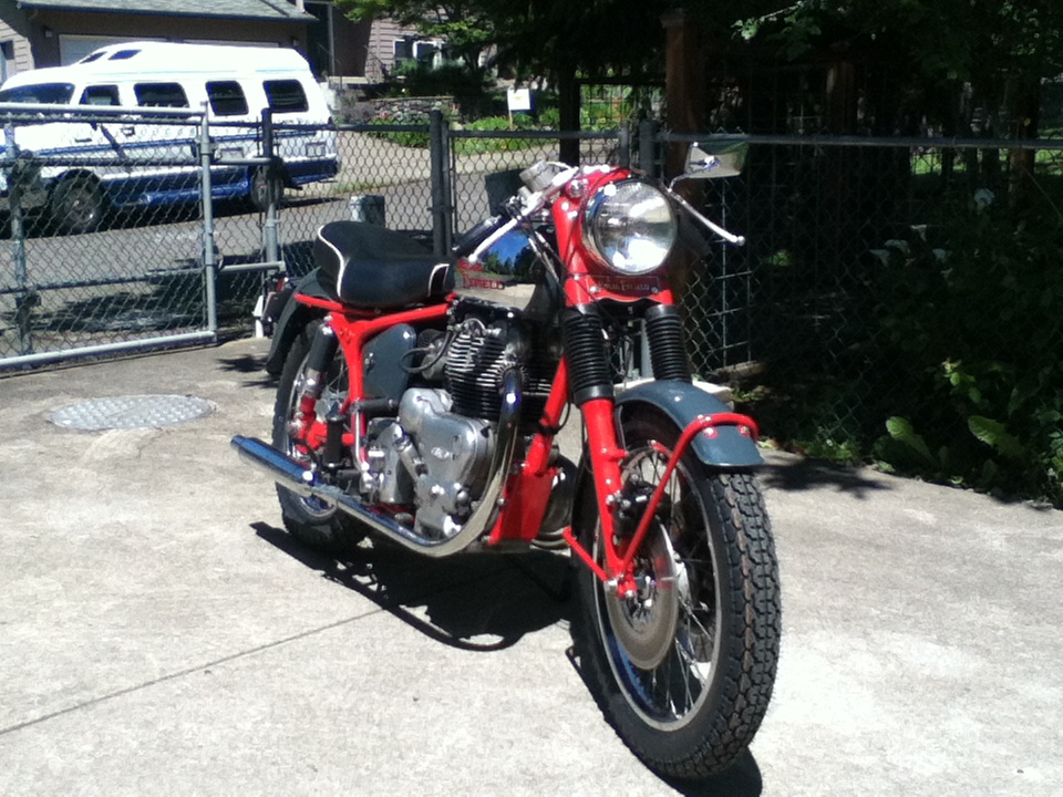
The Interceptor is finished. Like it or not.
I got a bit of grief over the color scheme.
"Too much red on the frame"
"Looks like gray primer"

It's what I wanted to do. End of story.

Included are some photos of my Enfield along with the bike that inspired me to go with the red/gray color scheme.
My friend  Ken's 1984 BMW R100, which he calls "Moto Espresso".  
The brighter red on mine with more exposed frame than the R100 is the reason I got some negative reactions. My bike did take 3rd place in its class at the Oregon Vintage Motorcyclists 33rd Annual Show, so I know that some folks like it as much as I do.


I'll be taking a break to work on some neglected projects around the house, and maintenance on my basic transportation  motorcycle, so it will be another "while" before I update this blog, but I should be well into the restoration of the Tomahawk by then. Plan on seeing a freshly powder coated gray frame and parts.

Thursday, May 10, 2012

Just over one week to go before the Interceptor has to be finished.

I've finally got the motorcycle assembled, less the engine.

I trued the back wheel last week. That's the first time for me. I've laced quite a few wheels, but always thought it would be best to have someone who's done it before handle the truing of all the wheels I've laced in the past.
I decided to give it a try,  even though I don't own a truing stand. Or, at least I thought I didn't own a truing stand.
Turns out, any motorcycle can also be a truing stand for wheels. Here's how I did it.
Back wheel mounted in the frame, minus the tire, and a small hobbyist bar clamp with the bar extended to where it just barely touches the wheel rim to serve as a pointer.
Rotate the wheel, and note where the rim is furthest from and closest to the pointer.
Tighten the spokes on the sections where it's away from the pointer, and loosen the spokes where it's close to the pointer.
This was a lot easier than I expected, and I had the wheel within factory specification for both run-out and concentricity within a half hour or so. Below is a photo of my "truing stand" and "pointer".

I finally got the last of the parts back from the powder coater. The front fender stays, two little covers for the tops of the forks, and several parts for the 1958 Tomahawk.
This allowed me to finally put the bike together for good. Filled the forks with oil, and verified they don't leak, then assembled them with all the parts; fork gaiters, fenders, fender stays, wheel.
Put the back wheel and tire on, and the sidestand, and I dropped the bike off my jack and onto its own two wheels.
This weekend, I'll be cleaning up the engine and maybe early next week, install it in the frame. I still have to put the wiring together, but that will be easy. I can use the old wires, and I have some nifty coves that split open to insert the wire, then just wrap around the wire so it looks like it was pulled through.

Here it is so far. The gas tank was hung on just to give it a more finished look. That's got to come off for fitting of the engine and completion  of the wiring.


I'll be posting again before next weekend, hopefully,  with photos of the finished bike.
Some assembly required.

Adapting Suzuki GT 750 forks (or any other Japanese fork with 35mm stanchion tubes) to fit a Royal Enfield.

Step #1.
Cut a thread at the top of the fork to allow it to screw into the threaded hole in the upper fork crown on the R-E.
This is a British Cycle thread, 26 threads per inch, 60 degree angle. 

 Here's one of the threaded holes in the upper fork crown which the stanchion tubes thread into.
 You need a short section at the top which is cut back to the root diameter of the thread.

Step #2
Modify the hex plugs at the top of the Suzuki stanchion tubes so they fit flush. This was complicated by the fact that the plugs are hollow, and cutting off the hex section at the end exposes the hollow. We worked around this by drilling the hole and tapping it with a 1/2 inch pipe thread, which we then filled with a hex socket pipe plug.
The bonus to this is that it will allow us to unscrew the stanchion the same way as the original Enfield forks, using a large allen wrench.
Here are the plugs as modified.


 Here are a couple of shots of the fork crown with the Suzuki stanchion installed for a trial fit.
This view shows the top of the fork through the little hole that allows the fork to be unscrewed with an allen wrench.
Step #3, figure out how to hook up the plumbing for the dual disk brakes. When I bought these forks back around 1990, I didn't know that the early GT750's came with an excellent four-leading shoe drum brake, and by the time I'd learned about that, all the four leading shoe drum brakes had been snapped up by people customizing English motorcycles.
To adapt the plumbing from the Suzuki forks, I made up a little bracket to hold the "splitter" that routes the hose from the master cylinder/brake lever down to the dual disks.
The shape of the bracket is dictated by the fact that it has to fit directly under the  friction damper for the steering. Carefully cut out to just clear the damper. 

 Here's how it sits on the fork.
 Step #4. The Suzuki fork legs are spaced 3/16 of an inch  further apart than the Enfield fork legs, so to use the Suzuki forks in an Enfield triple clamp, you have to figure out some way to split the difference between the two fork legs.
We made up a 3/32 inch washer that pulls the wheel over that distance, and re-centers it. The brake disks just clear the fork sliders, and since the calipers are floating, no modification of their mounting was required.
Here's the axle  and  washer.  I used two right side axle spacers because the one on the left side is the speedometer drive. The washer wasn't really necessary, but it makes it easier to get the wheel centered in the forks.


Step #5 (optional), you won't fool any British motorcycle enthusiasts, but your Enfield will look pretty cool if you make up some little badges to replace the pieces of tape stuck to the brake calipers that say "Suzuki" on them.


Here's a shot of the forks assembled and ready to go.


Forgot to mention the gaiters! They're Triumph gaiters with a flange on the inside bottom edge, which engages a groove in the fork slider. We had to cut a suitable groove in the top of the Suzuki fork leg.
I also used part of the tubes from the top of the Suzuki forks that hold the headlamp mounts to give me something to put the tops of the gaiters over. It attaches the same way as the standard Enfield upper fork covers, using little tabs which are held by the bottom fork crown pinch bolts.

Thursday, May 3, 2012


The forks are finally done! 
May 4th. Less than 3 weeks to go before the OVM show that I plan to display this thing at.
I've spent more time on these things than  any other single part of this project.
A couple of finish details, and I'll finally be ready to assemble them for good.
Tomorrow, I'm dropping the last few bits off for powder coating. I got the gas tank and fenders painted dark grey. Sadly, I'll probably have to get them redone, the painter I hired left a bit of an orange peel finish. I think he mixed too high a ratio of curing agent.
I might have a go at rubbing it down. I've done that on my rattle can paint jobs before, and it always works out pretty well.
The engine is on the workbench getting cleaned up, and I ordered some gaskets and a few nuts and bolts to make it look better. I'll be sandblasting and painting the cylinders black this weekend.

The rear wheel is ready for truing and a tire. I'll clean up the Suzuki front wheel and get a tire for it too.

I've verified that one of the two late-70's Kawasaki rectifier/regulator modules that I got from Cycle Psycho M/C Wreckers is functional. The other one rectifies, but it doesn't regulate. Just passes the input voltage straight through as a DC voltage. Oh well, one out of two is better than none out of two. I'll worry about the other one later.

The rear shocks have been cleaned up and reassembled. I have four Armstrong shocks. All of them with good damping, and the springs seem ok. I wasn't paying close attention when  I took them apart, and it wasn't until I was sandblasting the springs that I noticed that two of the springs are shorter than the other two. I just assumed these things were identical.
Holding a long and a short spring next to each other, the coils line up perfectly, so the short ones aren't just sagging from age, they were made shorter. Two fewer coils than the longer ones.
I suspect they came off a Meteor Minor 500 twin. Those were based on a 250cc Enfield with the 500cc engine in it.
The problem is that the damper rods are also different lengths, as are the painted covers that go over the springs. Guess which pair got painted red to match the Interceptor's frame color?
The short ones.
Guess which covers got painted gray to match the Tomahawk's planned frame color? That's right, the long ones!
So, I put the red shocks on the Interceptor with the gray  covers. Not what I planned, but it works out alright, because of the rest of the sheet metal for the Interceptor being gray.

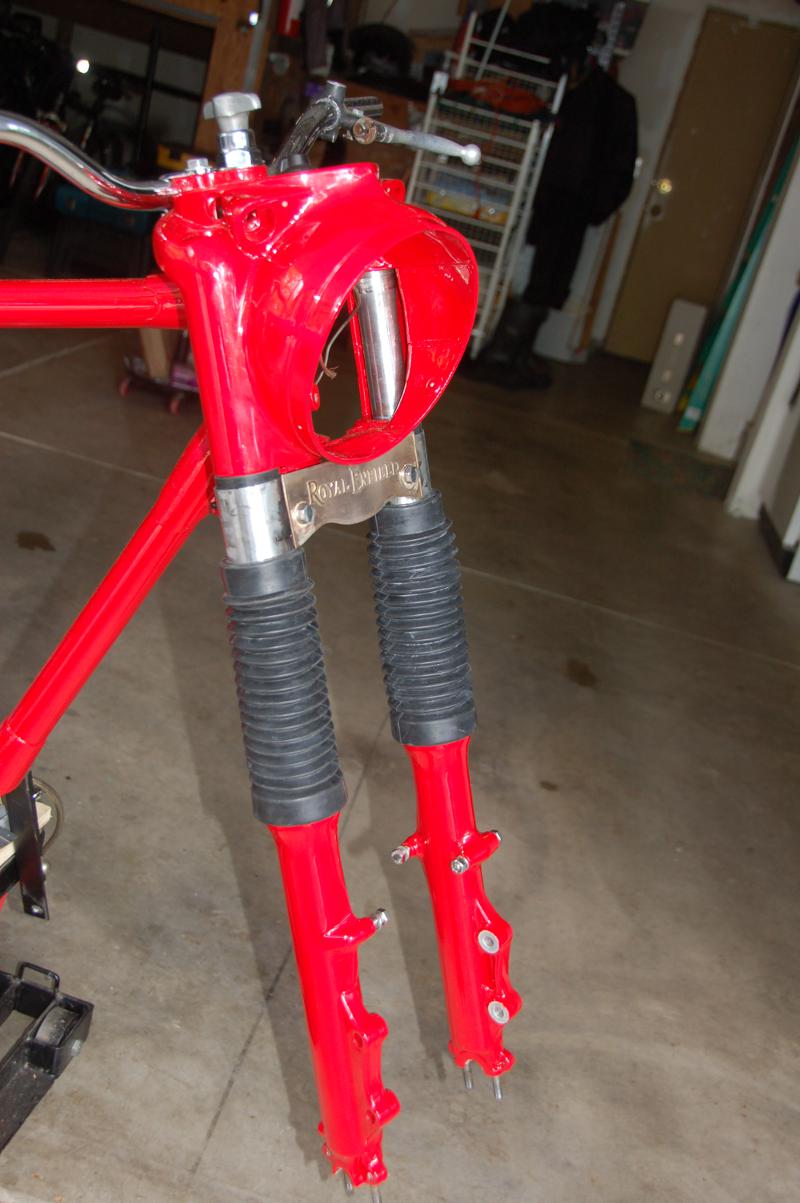
So here are the forks with all the bits. I still need to powder coat the little top cover tubes, and my "fork bridge" Royal Enfield badge needs to get some red enamel added to it. Then I'll nickel plate it.
Later, I plan to do an entire post covering what I did to make the forks go together.

Two views of the forks with all the bits installed.
The custom made fork bridge. Etched nickel copper bronze.


The red shocks with gray covers.


Sunday, April 8, 2012

Front fork mockup.

I've got all the miscellaneous bits cleaned up and painted, so I'm going to start putting together a motorcycle.
One item that I've spent a lot of time on is the front forks. I'm very close to having the Suzuki GT750 forks adapted to work with the Enfield frame. The main part of that was threading the top ends of the stanchion tubes to screw into the Enfield cast aluminum upper fork crown.
That's done. I'm in the process of modifying the end plugs to work with this setup, and I decided to go ahead and assemble the forks so I could make sure the wheel and brake disks are going to work.
Here's a photo of the loosely assembled forks. I'm still waiting on the little upper cover tubes which conceal the bottom triple clamp, and provide something to clamp the tops of the fork gaiters to.


I'm managing to get a little work done every day. It's looking like I can manage to get this bike done by May 20th if I concentrate on it. Consequently, I've given up my goal of restoring both bikes by the target date. If I keep working on both, I'll end up with two incomplete bikes to take to our  show.  I'll see if I can change the title of the blog to "Restoring Two Enfields in Two Years".
I can probably pull that off now that I've got some momentum built up.
Stay tuned, this should start coming together pretty fast now.
4/9/2012 update:
Finally got a solution  to a problem that anyone who tries to restore a Royal Enfield  in a home shop will encounter; how to put the frame on a cheap motorcycle stand in a postioin that allows you to work on both ends of the bike, while being solidly supported at the same time.

I was getting tired of the frame wiggling around with that strap holding it to the stand, and now, in addition to being solidly supported by those angle iron brackets, I can begin setting up the rear suspension and attach the wheels once they're ready.

Wednesday, February 1, 2012

Still plugging away.

I'm trying to do at least something every day. Lots of little stuff needs attention, primarily small parts that need cleaning and painting.
To that end, I've built an extemporaneous spray painting booth in my garage. I'll be concentrating on getting all the miscellaneous bits that need paint taken care of within the next couple of weeks, so I don't have to live with this thing occupying half my working environment. I can't even get the door on that side of the garage open!
And my wife thinks she has a right to half the garage to park her car in! The nerve. Why can't she understand that garages are for storing junk and working on projects?

Sunday, November 27, 2011

All of my posts should be titled "it's been awhile"...

Even if it hasn't.

I've made a bit of headway with the Interceptor's front forks. Got some machine work done to adapt some foreign fork legs to fit the R-E casquette fork crown.

This involved cutting a 26 tpi thread at the top of the stanchion tubes to allow them to screw into the casquette. I also cut a groove into the tops of the sliders so that a standard BSA/Triumph style rubber fork gaiter will work on them. There's a lip at the bottom of each gaiter that mates with the grooves in the fork sliders.  (Note that my use of first person above doesn't mean that I actually did the machine work.  As the machinist who actually did the work would be among the first to agree, it's best that I never learn to use machine tools, I'm way too prone to making stupid mistakes!)

I also filed off the "Made in...." that was part of the fork slider castings.  These will be powder coated red to match the frame.

I'm now working on cleaning up a couple of rear brake drum/sproket/cush drive units.

I'm also tentatively looking at options for the damaged 500 crankcase. I've got a spare crankcase, but it  needs work too.
The oil drain plug, which is hollow, and encorporates a mesh strainer with internal passages to supply the engine oil to the feed pump is well and truly stuck. It's made of brass, and I suspect some kind of dis-similar metal type of electrolosis process for causing sufficient corrosion to bond it to the aluminum threads in the crankcase.
Someone had made attempts at removing it long before I acquired the crankcase at a swap meet, and corners are all worn off the hex head. I've used pb blaster, as much heat as I thought the crankcase would tolerate, various types of tools, including the last resort, drilling the head out and using a large easy-out.
Still stuck. To get this out is going to require carefully drilling as much of it away as possible, then somehow picking the remains out of the threads.
The question is, will this be easier and faster than getting the damaged cam tunnel in the other crankcase welded up?
It would be great if I could take the good half from  one and use it with the good half from the other. But they're line-bored as a pair, and each half of the crankcase is stamped with the same unique number. Mixing them up is a guarantee of failed bearings and short  lived pistons.