Sunday, January 15, 2017

Ha! I bet all ten of my followers have been just dying to know what's happened since my last post just over four years ago!
I'd almost forgotten I started this blog. A lot's happened since 2012. Most significant of which was my joining the ranks of the "gainfully unemployed" in retirement as of Sept. 30, 2015. 
A major consequence of retirement is that I seem to have less free time than ever. the good part about that is that most of my not-free time is spent doing things that I enjoy, and give me a sense of satisfaction.

I just looked at the statistics for this blog, and noticed that there were three visitors to it today, 395 in the last month, and over 19,000 for the life of the blog. Granted, probably most of those are web "spiders" gathering information for search indeces (sp? I only know that "indexes" is wrong too), but there may be a few real humans actually paying attention, so here's an important update:

I'm working on the other Enfield! Seriously. Ok, "Two Royal Enfields in five/six years"? 
I've always had trouble stopping my work to take pictures, and when my workday is finished, I really don't feel like sitting down and writing about it, so very little of this is documented.  I'm just a shitty blogger, and nothing I can do about it.
Stay tuned, I'll gather up the few pictures I have of my progress so far, and post them here later. 


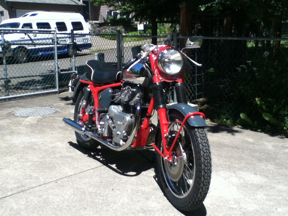
Here it is partially assembled, sitting next to the Interceptor to show off the color co-ordination.
Since this picture was taken, I've installed the polished alloy mudguards, and I've dropped the seat frame off for a new cover to be made.


Tuesday, December 4, 2012

I think I forgot to post a picture of the completed "fork bridge".


Instead of real enamel, I used an epoxy based material that's supposed to be easier to work with than enamel because you don't need to fire it at 1500 deg. F.
As someone who works with real kiln fired enamel, I can tell you that's completely wrong! This stuff is a pain in the @ss to work with compared to vitreous enamel.
The only reason I used it is because it's less sensitive than enamel, which is essentially glass,  to flexing and vibration, which are definate concerns for something to be used an a British motorcycle!

Tuesday, November 6, 2012

Update, 11/5/2012

Nothing new with the 1958 Tomahawk. So many other projects going on right now.

But the Interceptor  has been getting some much needed attention. It quit running on it's maiden voyage. Turned out to be a failed magneto.
I'm clean out of usable magnetos, and I don't want to run up my credit card again until I've got it back to a zero balance. So I have to get creative.

There's this little Lucas DKX2 distributor, which came off the Tomahawk. I'd been planning on installing one of my K2F magnetos on that bike when  it's ready for an ignition system. I like being able to run with no battery and a dead alternator, given the record I've had with those Lucas alternators.
Now I've got to get two of them refurbished or replaced with one of the electronic ignition replacements. That will happen, but not for awhile.


In the meantime, I need to get the Interceptor running. It's been  sitting since early June, when it quit running.

I have to find a place to put a battery in my modified battery box, which was chopped up years ago to accomodate some air filters. I haven't ever had a battery in that bike since I first got it, and years ago, decided that it needed air filters more than space to put a battery, so I altered the box so that some air filters would fit.

The solution, now that I need a battery, is to find the smallest sealed battery I can find. The one I ended up with, from Batteries Plus, measures one inch by two inches by three inches.
It only puts out 2 AH at 12 volts. Not much, but it will at least live long enough to get the motor running.
Then I needed a coil. That was easy, I bought a 6 volt coil from one of the Domi-Racer sale catalogs years ago.
And a switch. There's a Lucas "long arm" light  switch that came with the Tomahawk which looks like it will do the job, and has nice screw-terminals to connect to.  I found another one just like it on ebay for $28.00.
This switch is set up so that it has three positions; OFF, LOW, HIGH. I found that I could bring the main 12V line up to the center of the switch, then connect the headlamp (no high/low, just low beam) to the 3rd terminal, and the ignition coil to the second terminal.
With the switch in the OFF postion, it's not making contact with either the 2nd or 3rd terminals, and power is disconnected completely. Switch to the LOW position, and I get power only to the ignition coil, and switched to the HIGH position, I get power to the ignition  coil and the headlamp. Perfect.
The switch


The next trick is to find a ballast resistor to reduce the voltage seen by the coil down to 6 volts to limit the amount  of heat it dissipates. I found a nice 2 watt resistor with a cast aluminum body forming a finned heat sink. Checking the resistance through the coil, I find that it's exactly 1.8 ohms. Almost a perfect voltage divider, maybe just a little more dropped across the coil than the resistor, but pretty close.
I connected the coil, resistor, and distributor up to a large battery charger with an ammeter, and found the total current draw was a bit less than 3 amps, with  about 4 volts dropped on the resistor, and 5 point something dropped on the coil.
On twisting the distributor, I got a nice, fat spark out of each sparkplug. I left the whole thing connected to the charger for about an hour with the points closed, and checked the resistor and coil periodically to see how warm they got.
They both seemed to reach a maximum temperature that was reasonable; I could pick them up without burning my fingers.
In looking around for a way to install the resistor, I came across a piece of 1 inch aluminum  angle "iron". This could mount to the vertical piece inside the battery box which holds the battery strap in place (which I'm using to hold the ignition coil in place, because the battery is now in the other side of the box). I pop-riveted the resistor to this, and hooked everything back up to the battery charger. The resistor was now running  noticably cooler, while the aluminum drew heat off of it.
The little battery, seen from one end, along with the Kawasaki KZ650 rectifier/regulator.
 Battery in it's protective layer of foam plastic, the terminal strip where everything hooks up,  and the rec/reg module, all inside the right-hand side of the battery/toolbox.
 The ignition coil in its foam jacket, held in place by the battery strap, and the resistor on it's heat sink/mounting bracket. A little crude, but it's all covered up by the toolbox covers.
The wires feeding the distributor from the coil ready to be hooked up.


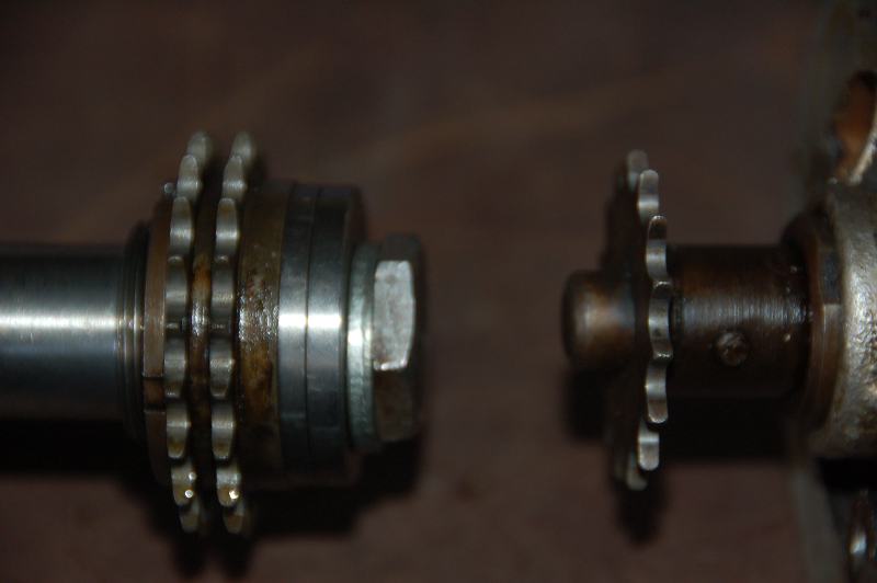
Another issue with this setup is that the K2F magneto on Royal Enfields is driven by a double row chain, while the KDX distributor is driven by a single row chain. Both chains seem to have the same pitch, but the sprockets don't align, and in addition, the distributor drive sprockets are smaller than the magneto drive sprockets.
This means I have to use the Tomahawk's intake cam sprocket, because the intake sprocket also carries the ignition  drive sprocket.
Also, on inspecting the single row chain that came out of the Tomahawk, I found one link plate had broken. This bike was parked just before a major failure, apparently. I don't seen how that chain could last 10 minutes in a running engine.
Fortunately, those are available from Hitchcock's in England. While I ordered that, I decided to get a new timing chain as well. The one I had in there is pretty stretched.

New timing chain
 Note the broken plate on the lower run near the center.
 The single row ignition drive sprocket
 Double and single row ignition driven sprockets.
 Double row ignition drive sprocket.


Sunday, June 10, 2012

Halfway there.

The Interceptor is finished. Like it or not.
I got a bit of grief over the color scheme.
"Too much red on the frame"
"Looks like gray primer"

It's what I wanted to do. End of story.

Included are some photos of my Enfield along with the bike that inspired me to go with the red/gray color scheme.
My friend  Ken's 1984 BMW R100, which he calls "Moto Espresso".  
The brighter red on mine with more exposed frame than the R100 is the reason I got some negative reactions. My bike did take 3rd place in its class at the Oregon Vintage Motorcyclists 33rd Annual Show, so I know that some folks like it as much as I do.


I'll be taking a break to work on some neglected projects around the house, and maintenance on my basic transportation  motorcycle, so it will be another "while" before I update this blog, but I should be well into the restoration of the Tomahawk by then. Plan on seeing a freshly powder coated gray frame and parts.

Thursday, May 10, 2012

Just over one week to go before the Interceptor has to be finished.

I've finally got the motorcycle assembled, less the engine.

I trued the back wheel last week. That's the first time for me. I've laced quite a few wheels, but always thought it would be best to have someone who's done it before handle the truing of all the wheels I've laced in the past.
I decided to give it a try,  even though I don't own a truing stand. Or, at least I thought I didn't own a truing stand.
Turns out, any motorcycle can also be a truing stand for wheels. Here's how I did it.
Back wheel mounted in the frame, minus the tire, and a small hobbyist bar clamp with the bar extended to where it just barely touches the wheel rim to serve as a pointer.
Rotate the wheel, and note where the rim is furthest from and closest to the pointer.
Tighten the spokes on the sections where it's away from the pointer, and loosen the spokes where it's close to the pointer.
This was a lot easier than I expected, and I had the wheel within factory specification for both run-out and concentricity within a half hour or so. Below is a photo of my "truing stand" and "pointer".

I finally got the last of the parts back from the powder coater. The front fender stays, two little covers for the tops of the forks, and several parts for the 1958 Tomahawk.
This allowed me to finally put the bike together for good. Filled the forks with oil, and verified they don't leak, then assembled them with all the parts; fork gaiters, fenders, fender stays, wheel.
Put the back wheel and tire on, and the sidestand, and I dropped the bike off my jack and onto its own two wheels.
This weekend, I'll be cleaning up the engine and maybe early next week, install it in the frame. I still have to put the wiring together, but that will be easy. I can use the old wires, and I have some nifty coves that split open to insert the wire, then just wrap around the wire so it looks like it was pulled through.

Here it is so far. The gas tank was hung on just to give it a more finished look. That's got to come off for fitting of the engine and completion  of the wiring.


I'll be posting again before next weekend, hopefully,  with photos of the finished bike.
Some assembly required.

Adapting Suzuki GT 750 forks (or any other Japanese fork with 35mm stanchion tubes) to fit a Royal Enfield.

Step #1.
Cut a thread at the top of the fork to allow it to screw into the threaded hole in the upper fork crown on the R-E.
This is a British Cycle thread, 26 threads per inch, 60 degree angle. 

 Here's one of the threaded holes in the upper fork crown which the stanchion tubes thread into.
 You need a short section at the top which is cut back to the root diameter of the thread.

Step #2
Modify the hex plugs at the top of the Suzuki stanchion tubes so they fit flush. This was complicated by the fact that the plugs are hollow, and cutting off the hex section at the end exposes the hollow. We worked around this by drilling the hole and tapping it with a 1/2 inch pipe thread, which we then filled with a hex socket pipe plug.
The bonus to this is that it will allow us to unscrew the stanchion the same way as the original Enfield forks, using a large allen wrench.
Here are the plugs as modified.


 Here are a couple of shots of the fork crown with the Suzuki stanchion installed for a trial fit.
This view shows the top of the fork through the little hole that allows the fork to be unscrewed with an allen wrench.
Step #3, figure out how to hook up the plumbing for the dual disk brakes. When I bought these forks back around 1990, I didn't know that the early GT750's came with an excellent four-leading shoe drum brake, and by the time I'd learned about that, all the four leading shoe drum brakes had been snapped up by people customizing English motorcycles.
To adapt the plumbing from the Suzuki forks, I made up a little bracket to hold the "splitter" that routes the hose from the master cylinder/brake lever down to the dual disks.
The shape of the bracket is dictated by the fact that it has to fit directly under the  friction damper for the steering. Carefully cut out to just clear the damper. 

 Here's how it sits on the fork.
 Step #4. The Suzuki fork legs are spaced 3/16 of an inch  further apart than the Enfield fork legs, so to use the Suzuki forks in an Enfield triple clamp, you have to figure out some way to split the difference between the two fork legs.
We made up a 3/32 inch washer that pulls the wheel over that distance, and re-centers it. The brake disks just clear the fork sliders, and since the calipers are floating, no modification of their mounting was required.
Here's the axle  and  washer.  I used two right side axle spacers because the one on the left side is the speedometer drive. The washer wasn't really necessary, but it makes it easier to get the wheel centered in the forks.


Step #5 (optional), you won't fool any British motorcycle enthusiasts, but your Enfield will look pretty cool if you make up some little badges to replace the pieces of tape stuck to the brake calipers that say "Suzuki" on them.


Here's a shot of the forks assembled and ready to go.


Forgot to mention the gaiters! They're Triumph gaiters with a flange on the inside bottom edge, which engages a groove in the fork slider. We had to cut a suitable groove in the top of the Suzuki fork leg.
I also used part of the tubes from the top of the Suzuki forks that hold the headlamp mounts to give me something to put the tops of the gaiters over. It attaches the same way as the standard Enfield upper fork covers, using little tabs which are held by the bottom fork crown pinch bolts.

Thursday, May 3, 2012


The forks are finally done! 
May 4th. Less than 3 weeks to go before the OVM show that I plan to display this thing at.
I've spent more time on these things than  any other single part of this project.
A couple of finish details, and I'll finally be ready to assemble them for good.
Tomorrow, I'm dropping the last few bits off for powder coating. I got the gas tank and fenders painted dark grey. Sadly, I'll probably have to get them redone, the painter I hired left a bit of an orange peel finish. I think he mixed too high a ratio of curing agent.
I might have a go at rubbing it down. I've done that on my rattle can paint jobs before, and it always works out pretty well.
The engine is on the workbench getting cleaned up, and I ordered some gaskets and a few nuts and bolts to make it look better. I'll be sandblasting and painting the cylinders black this weekend.

The rear wheel is ready for truing and a tire. I'll clean up the Suzuki front wheel and get a tire for it too.

I've verified that one of the two late-70's Kawasaki rectifier/regulator modules that I got from Cycle Psycho M/C Wreckers is functional. The other one rectifies, but it doesn't regulate. Just passes the input voltage straight through as a DC voltage. Oh well, one out of two is better than none out of two. I'll worry about the other one later.

The rear shocks have been cleaned up and reassembled. I have four Armstrong shocks. All of them with good damping, and the springs seem ok. I wasn't paying close attention when  I took them apart, and it wasn't until I was sandblasting the springs that I noticed that two of the springs are shorter than the other two. I just assumed these things were identical.
Holding a long and a short spring next to each other, the coils line up perfectly, so the short ones aren't just sagging from age, they were made shorter. Two fewer coils than the longer ones.
I suspect they came off a Meteor Minor 500 twin. Those were based on a 250cc Enfield with the 500cc engine in it.
The problem is that the damper rods are also different lengths, as are the painted covers that go over the springs. Guess which pair got painted red to match the Interceptor's frame color?
The short ones.
Guess which covers got painted gray to match the Tomahawk's planned frame color? That's right, the long ones!
So, I put the red shocks on the Interceptor with the gray  covers. Not what I planned, but it works out alright, because of the rest of the sheet metal for the Interceptor being gray.

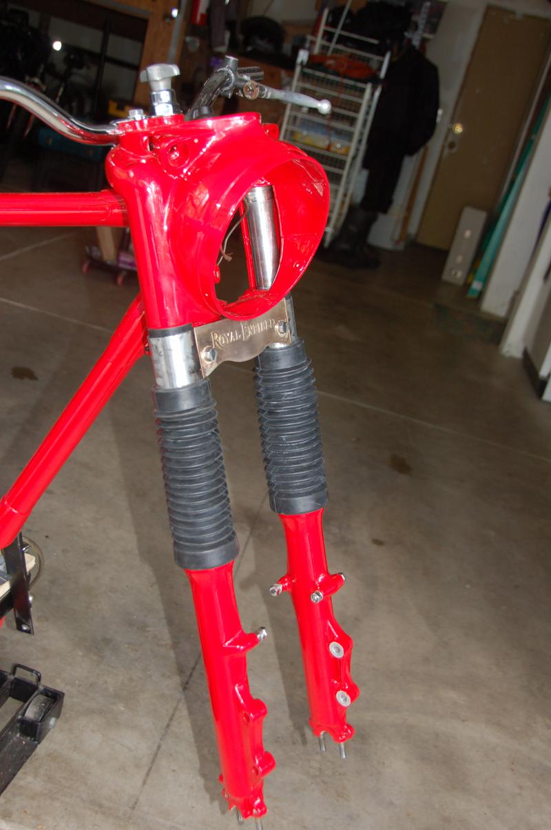
So here are the forks with all the bits. I still need to powder coat the little top cover tubes, and my "fork bridge" Royal Enfield badge needs to get some red enamel added to it. Then I'll nickel plate it.
Later, I plan to do an entire post covering what I did to make the forks go together.

Two views of the forks with all the bits installed.
The custom made fork bridge. Etched nickel copper bronze.


The red shocks with gray covers.


Sunday, April 8, 2012

Front fork mockup.

I've got all the miscellaneous bits cleaned up and painted, so I'm going to start putting together a motorcycle.
One item that I've spent a lot of time on is the front forks. I'm very close to having the Suzuki GT750 forks adapted to work with the Enfield frame. The main part of that was threading the top ends of the stanchion tubes to screw into the Enfield cast aluminum upper fork crown.
That's done. I'm in the process of modifying the end plugs to work with this setup, and I decided to go ahead and assemble the forks so I could make sure the wheel and brake disks are going to work.
Here's a photo of the loosely assembled forks. I'm still waiting on the little upper cover tubes which conceal the bottom triple clamp, and provide something to clamp the tops of the fork gaiters to.


I'm managing to get a little work done every day. It's looking like I can manage to get this bike done by May 20th if I concentrate on it. Consequently, I've given up my goal of restoring both bikes by the target date. If I keep working on both, I'll end up with two incomplete bikes to take to our  show.  I'll see if I can change the title of the blog to "Restoring Two Enfields in Two Years".
I can probably pull that off now that I've got some momentum built up.
Stay tuned, this should start coming together pretty fast now.
4/9/2012 update:
Finally got a solution  to a problem that anyone who tries to restore a Royal Enfield  in a home shop will encounter; how to put the frame on a cheap motorcycle stand in a postioin that allows you to work on both ends of the bike, while being solidly supported at the same time.

I was getting tired of the frame wiggling around with that strap holding it to the stand, and now, in addition to being solidly supported by those angle iron brackets, I can begin setting up the rear suspension and attach the wheels once they're ready.

Wednesday, February 1, 2012

Still plugging away.

I'm trying to do at least something every day. Lots of little stuff needs attention, primarily small parts that need cleaning and painting.
To that end, I've built an extemporaneous spray painting booth in my garage. I'll be concentrating on getting all the miscellaneous bits that need paint taken care of within the next couple of weeks, so I don't have to live with this thing occupying half my working environment. I can't even get the door on that side of the garage open!
And my wife thinks she has a right to half the garage to park her car in! The nerve. Why can't she understand that garages are for storing junk and working on projects?

Sunday, November 27, 2011

All of my posts should be titled "it's been awhile"...

Even if it hasn't.

I've made a bit of headway with the Interceptor's front forks. Got some machine work done to adapt some foreign fork legs to fit the R-E casquette fork crown.

This involved cutting a 26 tpi thread at the top of the stanchion tubes to allow them to screw into the casquette. I also cut a groove into the tops of the sliders so that a standard BSA/Triumph style rubber fork gaiter will work on them. There's a lip at the bottom of each gaiter that mates with the grooves in the fork sliders.  (Note that my use of first person above doesn't mean that I actually did the machine work.  As the machinist who actually did the work would be among the first to agree, it's best that I never learn to use machine tools, I'm way too prone to making stupid mistakes!)

I also filed off the "Made in...." that was part of the fork slider castings.  These will be powder coated red to match the frame.

I'm now working on cleaning up a couple of rear brake drum/sproket/cush drive units.

I'm also tentatively looking at options for the damaged 500 crankcase. I've got a spare crankcase, but it  needs work too.
The oil drain plug, which is hollow, and encorporates a mesh strainer with internal passages to supply the engine oil to the feed pump is well and truly stuck. It's made of brass, and I suspect some kind of dis-similar metal type of electrolosis process for causing sufficient corrosion to bond it to the aluminum threads in the crankcase.
Someone had made attempts at removing it long before I acquired the crankcase at a swap meet, and corners are all worn off the hex head. I've used pb blaster, as much heat as I thought the crankcase would tolerate, various types of tools, including the last resort, drilling the head out and using a large easy-out.
Still stuck. To get this out is going to require carefully drilling as much of it away as possible, then somehow picking the remains out of the threads.
The question is, will this be easier and faster than getting the damaged cam tunnel in the other crankcase welded up?
It would be great if I could take the good half from  one and use it with the good half from the other. But they're line-bored as a pair, and each half of the crankcase is stamped with the same unique number. Mixing them up is a guarantee of failed bearings and short  lived pistons.

Friday, October 7, 2011

A pair of alloy mudguards (fenders, to us yanks) came in today.

Bought them from www.nfieldgear.com the online shop for the US Royal Enfield distributor.
The fact that there are new parts made in India which will substitute for missing parts on our old Enfields is such a luxury after so many years of scrounging and making do when parts aren't readily available.  These fenders cost all of $135 + about $30 for shipping. Can't get any cheaper than that, and the quality is more than acceptable.

The fenders aren't for the Interceptor, which is a good thing. Then the bike would look too much like this Enfield, owned by a fellow Enfield enthusiast, which happens to have the same fenders as the ones I just recieved. I'm really not copying this bike, although I really admire it. Once I'm done with the Interceptor, you'll see what I mean.  This picture is just so you can see what the alloy fenders look like.


I guess I didn't mention it yet, but the plan is to do the bikes in the same colors, but with the color  scheme reversed, so the Indian will get a silver grey frame with red sheet metal (except for those alloy fenders!), and the Interceptor will have the red frame and silver-grey sheet metal.

My rationale for doing them this way is that the Interceptor, being more of a custom bike has a lot more room for playing around with colors, so it gets a red frame. The Tomahawk, I've decided, is going to go back to a more original configuration, which had red sheet metal, with alloy fenders. All the frame parts should be black, but I decided to customize it just a touch so that when I put both bikes together, they look like a matched pair.

Thursday, October 6, 2011

Long Time No See

At this point, I'm fully recovered from my medical issue, and trying to get back to my life. Finally starting to get serious here.

I have the wheels nearly ready to go. Bought  all new wheel bearings, polished the brake plates, and I just have to get them trued up, and they're ready for tires.


I also took one of the frames in and had it powder coated. Red. This is the Interceptor, and since it's not going to be anywhere near original, I figure I can play around with the colors on it.

The fenders and other sheet metal parts will be done in a silver-grey for contrast.

Here's a photo of the frame parts I had powder coated. The picture turned out looking very orange for some reason. There's definately an orange cast to this color, but not as bad as it looks.


A little progress. Let's see if I can gain some momentum on this thing now.

Sunday, August 14, 2011

Been awhile....

I wonder if this blog has been abandoned long enough to be picked up by that artist in New York who has a blog about abandoned blogs?
Prolly not.

I haven't made much progress in the last month. I had to go to the hospital for major surgery on July 14th, and when they discharged me, it was under the condition that I not lift anything heavier than 10 lbs, and limit my activity.

So, as of Thursday, the 11th, the restrictions are lifted, so I'm back in the garage. Found someone to repair the damage that I found in the Tomahawk's crankcase. I just need to get it clean for him.  Welding on these is tricky, and this guy is supposedly a welder that other welders go to when they get stuck on a job.

I've also been working on wheels. I did most of the work before I went in for surgery, but I just finished lacing up the last of three wheels. Two of them for the Tomahawk, and one for the Interceptor.

New stainless spokes from Buchanan's, and polished up the aluminum hubs.
I'm not aiming for 100 point Pebble Beach Concourse quality, more like "cool bike" at the Pizza place on "bike night" quality.

Here's what they look like so  far. I still need to get new bearings in them all, and the rear wheels need the drive sprockets and brake plates cleaned up. The one  front  wheel of the three has had the brake plates polished (double-sided brake drum), but still needs the brake parts cleaned up and put back together.

Lacing  these after having them apart for 6 months was an interesting excersize. Two of them laced up pretty easily, using the same pattern as the BMW wheels I did back in May. (also the same as some BSA 441 wheels that I have on hand)  These were the 19 inch wheels on the Tomahawk.
When I tried to do the 18 inch rear wheel from the Interceptor, the spokes just didn't seem to want to work out. I ended up with all the inner spokes on one side being way too long, and all the outer spokes on the other side way too short.
I check of my Interceptor shop manual, and the  Indian Tomahawk/Trailblazerl/Apache manual didn't have a lot to say  about spoke lacing, except that  the Interceptor front and rear wheels are laced in "one over two" pattern. While the Indian  front wheel is laced "one over two" and the rear wheel is laced "one over three".   I presume that's the number of other spokes that each spoke crosses over.
I looked up several websites that describe  wheel lacing techniques, and none of them specifically said what these terms mean. They were all bicycle enthusiast sites, which described many different patterns, most of them probably completely inappropriate to motorcycle wheel building. 
The two wheels that laced up easily were laced with all the inner spokes (the ones you put in first) on both sides angled the same direction in relation to the hub, and all the outer spokes laced the opposite direction. This is also how BMW /2 spokes lace up.
I decided to try alternating the inner and outer sets of spokes in relation to each other on the Interceptor's wheel, so that the inner spokes on one side of the wheel were angled the same direction as the outer spokes on the other side of the wheel, and vice-versa for the other sets of inner/outer spokes.
Went together very nicely that way, and I think you can see the difference in the lacing pattern when  you look at the wheels.  The oddball pattern is the bottom picture. 
I'm not sure why the Interceptor back wheel is different, it should have been the Tomahawk rear wheel that's different. The 18 inch rim  I used on the Interceptor is the one that's been on it since I put the bike together in 1972, but it's a replacement rim, laced up by a guy who worked for the Royal Enfield dealer in Atherton, California, near where I lived when I bought the bike. Could be the rim was drilled in a non-standard pattern compared to an original Interceptor rear wheel.
As for the Tomahawk rear wheel lacing up the same as the front wheel, that's probably because I'm using the 19 inch front rim off the Interceptor.  I took the best three of the 6 old rims I had available, and must have ended up with two front rims. No big deal, there's no difference other than the lacing pattern necessitated by how they're drilled for the spokes.

Tomahawk 19 inch rear wheel


Tomahawk Front  Wheel

Interceptor Rear Wheel

The rims are original. They were good enough for my standards to use with just a good cleaning with 000 steel wool and WD40.  A few nicks, but no rust pitting, and the chrome isn't peeling anywhere.

Tuesday, June 21, 2011

Another distraction. VAX Interceptor discovered in a barn!

My barn. Some parts that I bought back around 1975 or so have been identified as the most important parts of a very rare model of Royal Enfield.

When I first heard about the 1960 Royal Enfield 700cc Interceptor, I attempted to argue with the guy who told me about them. Turns out they're real. Enfield was working on the Interceptor design, and built a few prototypes using a hot-rodded Constellation engine, and shipped them to the US in 1960, two years before the formal introduction of the 750 Interceptor.
According  to the wikipedia article about Interceptors they made 163 of them. Other sources put the number at 170 and 211. According to Burton Bike Bits Interceptor Registry there are only 9 (not counting this one) known to exist, either as complete bikes or as correctly numbered crankcases or frames. Mine would make 10.
I discovered what this was after I sent a list of engine numbers for crankcases that are in my possession to the REOC-UK to help them update a database they're compiling based on factory records vs what is known to exist now.
The  following is copies of part of an email exchange I had with the REOC president regarding the engine and frame numbers that I sent to him.

Hi Carl,

Thank you for the engine numbers.

We didn't have any of the YB numbers you gave, so that's another three added to the listing.
This unfortunately also means that I cannot date or verify your comlete machine as it is not in our records - will have to assume that it is an original pair for now.

The damaged cases with a VAX number are from a 700cc Interceptor despatched in April 1960.

Your Tomahawk is even more interesting as the frame number has nothing recorded against it in the ledgers. The machines either side have similar engine numbers to yours, however, so it is an original machine although it was probably despatched in 1957, possibly '58 but definitely not '59.

As we do not have this machine in the records, I would most grateful if you could take a picture of the complete bike and close ups of the frame / engine numbers and let me have them as email attachments.

Please let me have the numbers of the frames you have as well - I can let you know what they are (hopefully) and annotate our records that the bike has been broken up.

Regards,

Graham
I was asked to send in any frame numbers that I had, which I did.

Graham, I've found three Enfield frames in my collection of parts that I
forgot that I had.

I think they're all 500 or 700 twin frames.

The numbers are 6828, 7651, and 11051.

The two lower numbered ones don't have the large plate-type head steady
lug welded to the main tube. 11051 does have one of these, plus holes
for the triangular aluminum block behind the gearbox. It has an older
style swingarm with bronze bushings and grease fittings.

I hope this is of help in completing your records. Two of these frames,
6828 and 11051 are still usable, 7651 was "re-engineered" by some
shade-tree mechanic who thought an Enfield frame would work better as a
full-cradle frame. I'm afraid that if one was to cut off the crude lump
of pipe that was welded to the downtube, it would weaken the downtube
enough that it wouldn't be safe to use the frame.

I'd love to hear what model/year these frames are from.

Thanks,
Carl

The reply.

Hello Carl,

Thank you for the numbers.

7651 is a December '58 Apache (Brockhouse).

6828 could be either a May '58 Apache (Brockhouse) or a July '63 500 Sports
Twin (Shores).
I don't know enough about these to verify which one, even with a photo of
it.

11051 is an April '60 700cc Interceptor, often referred to as the "VAX"
model, this being the engine prefix.
All these engines had 60xxx numbers, but the damaged cases you have are not
from the engine originally fitted to this frame.

Regards,

Graham

After realizing that I had some potentially valuable parts, I dragged them out into the light, and realized that I'd misread the frame number, so I sent an email with the updated number.

Graham, I've got several people who are very interested in that vax
interceptor frame, so I got it out of storage to take some pictures, and
discovered that I'd misread the number.
It's 11059, not 11051.
Is this outside of the range for a VAX Interceptor?

Thanks,

Carl

Confirmed that I had an engine and frame which came from the same bike.

Hi Carl,

Assumption correct - your "corrected" frame number 11059 was indeed shipped
with engine VAX 60219 fitted during April 1960.

Regards,

Graham

Then I got to thinking about the number stamped on the front of the same engine. I'd been told that this number represented the number stamped on the gearbox that was originally shipped with the engine as parts of the same bike.
Once again, I discover that I had a serial numbered part that came from this same rare Royal Enfield.
Another piece of the puzzle dropped into place when I remembered that I had one crankcase with no number stamped on it. This was among the parts in the purchase I made which included the VAX Interceptor. It's believed that Enfield shipped un-numbered crankcases to their dealers to install when an engine wasn't found to be repairable. They were probably expected to stamp it with the number from the original engine. This crankcase was probably the replacement for the one that was broken by a thrown connecting rod. Why the original owner bothered to keep the broken one, I don't know, but it was a good decision.
Here are pictures of the parts I have to build a VAX interceptor. All the other parts can be obtained, either from newly manufactured parts, or used parts. I have most of the engine parts that are needed.
Now I need to decide if I want a third Royal Enfield project, or if I should pass this on to someone else.
I've recieved offers.

The frame:


The engine.


The gearbox.


The replacement engine:


There's one more email I should copy. The REOC president said he found the factory record for my Tomahawk. It had been mis-filed in the ledger for the 700cc bikes.
Hi Carl,

I have just chanced upon the entry for your Tomahawk in the factory ledgers.
Some fool wrote it up in the 700cc book, so I have transferred it into the correct 500cc file on my spreadsheets.

It left Redditch on 28th November 1957 for the Brockhouse depot in the UK, then on to USA.

Regards,

Graham